Written By: Val
Link To: Carb Removal and Shimming
Valve Adjustment Procedure:
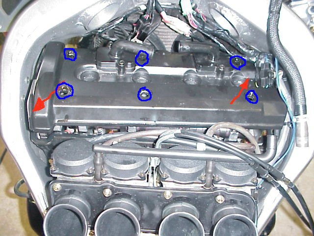 The photo shows the carbs still on the bike during valve cover removal. This can be done but I recommend at a
minimum slide the carbs towards the rear by loosening the 4 (3mm allen head screws). Then remove 6 (10mm) valve
cover bolts (blue) and remove the valve cover. I found the easiest technique to be lift the valve cover up and
push the right to the front and the left side to the rear (red arrows). What ever works for you...
The photo shows the carbs still on the bike during valve cover removal. This can be done but I recommend at a
minimum slide the carbs towards the rear by loosening the 4 (3mm allen head screws). Then remove 6 (10mm) valve
cover bolts (blue) and remove the valve cover. I found the easiest technique to be lift the valve cover up and
push the right to the front and the left side to the rear (red arrows). What ever works for you...
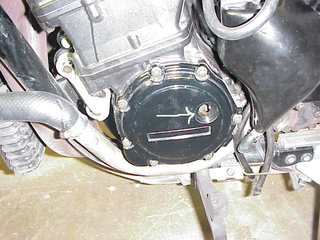 Okay now drop down and pull the sight window off the pickup coil sight window. A big standard screw driver
or can just grab a quarter and the pliers and back it out. I then roll the back tire and shift from 1st to 6th
using my left hand. It may take a few attempts but believe me you can do it. (Tire speed helps) Now for the hard
part. You’ve got to make a decision on whether you want to call the wife for a little help or just pull 4 spark
plugs. I normally opt for the later because I did the 5K shutdown and want to check the color of the plugs. If you
opt for the wife then have her look through the site window and look for the letters FT with the help of a flashlight.
Both letters will have a timing mark at the top and you need to line the T’s mark up with the one on the crankcase
mark. You’ll have it correct if together both marks form a straight line. Give the wife a kiss and tell he you will
need her again in 10 minutes with a beer.
Okay now drop down and pull the sight window off the pickup coil sight window. A big standard screw driver
or can just grab a quarter and the pliers and back it out. I then roll the back tire and shift from 1st to 6th
using my left hand. It may take a few attempts but believe me you can do it. (Tire speed helps) Now for the hard
part. You’ve got to make a decision on whether you want to call the wife for a little help or just pull 4 spark
plugs. I normally opt for the later because I did the 5K shutdown and want to check the color of the plugs. If you
opt for the wife then have her look through the site window and look for the letters FT with the help of a flashlight.
Both letters will have a timing mark at the top and you need to line the T’s mark up with the one on the crankcase
mark. You’ll have it correct if together both marks form a straight line. Give the wife a kiss and tell he you will
need her again in 10 minutes with a beer.
 Okay if you have lined up the timing marks correctly you either have #1 cylinder or #4 cylinder at TDC (Top Dead
Center). If you didn’t call the wife just take a flashlight and look in the spark plug hole. You will either see
the top of the piston in 1 or 4. If you decided to call the wife no big deal you just have to look at the cams and
it will tell you the answer.
Okay if you have lined up the timing marks correctly you either have #1 cylinder or #4 cylinder at TDC (Top Dead
Center). If you didn’t call the wife just take a flashlight and look in the spark plug hole. You will either see
the top of the piston in 1 or 4. If you decided to call the wife no big deal you just have to look at the cams and
it will tell you the answer.
When #4 is TDC the body (tip) of the cam lobes should not be touching the rocker arm (the dohickey the cam lobe
touches) on #2 and #4 intake and #3 and #4 exhaust.
If you look at the picture above you will see I am checking the #2 (right) exhaust valve. Also in the lower
right portion of the picture you will see #3 intake cam lobes are up meaning it can also be checked. I currently
have the motor at #1 TDC. This means I can check the clearance on #1 and #3 intake and #1 and #2 exhaust valves.
Each cylinder has 2 intake valves and 2 exhaust valves so you will end up checking 16 total valves before you are done.
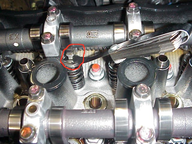
Look at the picture above and you will see that I am sliding the feeler gauge between the rocker arm and the shim.
Not the rocker arm and the cam. When you slide the feeler gauge between the rocker arm and shim it should slide without
resistance. Just because you can take an 8k feeler and stick it between the rocker arm and the shim doesn’t mean it is
out of clearance if you forced it. What should it feel like? Well when sliding the gauge if it feels like your scratching
the shim or the rocker arm then I would say your forcing it.
All valves aren’t as easy to check as #2 and #3 cylinders. It’s crowded in there and you may think it isn’t possible
but it is.
| Valve | Minimum | Maximum |
|---|
| Exhaust | 0.18mm (0.0071") | 0.24mm (0.0095") |
|---|
| Intake | 0.13mm (0.0051") | 0.19mm (0.0075") |
|---|
If your feeler gauge is only broken down into thousands IE.. .005 and .006 and doesn’t have a .0005 or .0001 blade
don’t panic. The gauge I use has .005 and .007 on the same blade.
Well it’s been 10 minutes and you’ve checked 8 valves. Wife shows up and you have her watch for the mark to come
around again. If it only spun one revolution you will now be able to check the valves you didn’t check the first time.
Her assistance is no longer needed unless you just want her to shuttle beers every 30 minutes.
What if while checking the #4 intake the 7k feeler goes without resistance? Then take the 8k feeler and use it.
If it has resistance then I would say your good to go. Might want to remember this valve because it may or may not
be out next time you adjust valves. If the 8k slides without any resistance try the 9k. Keep checking until you get
resistance. After you get the upper limit you then need to remove the shim and replace it with another. Let's just say
for this example it is between an 8k and 9k. Well now we need to do some math. On your feeler gauge hopefully you will
have the mm equivalent of the inch measurement you are using. If you’re using mm to begin with then you’re ahead of
the game. .008in = .203mm and .009in = .229mm The difference in mm is .026mm. We know the clearance is in the middle
so lets just say it is .0085in or .216mm. (I just added .013mm to .203mm.)
.216mm current gap /// .19mm is the upper limit in the book////
We need a thicker shim.
The current valve is out of clearance .026mm and shims come in .05mm increments so the next size up should do the trick..
We estimated it was gapped at .216 and if you subtract .05mm you get .166mm
This will put us in the window of .13mm and .19mm used for intake valves.
So now we need to remove the shim and determine the size.
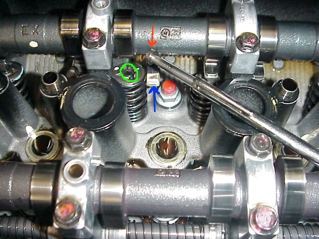 In the picture above you will see I slid the rocker arm over and lowered it so it will rest on the valve spring.
I then took a magnet and removed the shim. On one side of the shim you will find two digits. The numbers should
have been on the opposite side of the rocker arm. Lets say your shim has the number 75 on it. This number is not
a true measurement but a reference number to use when replacing it and numbers are in increments of 5. A shim
with the numbers 70 would be thinner in thickness and 80 would be thicker. We need a larger shim so we want an 80.
Go to your local Kawasaki Stealership and show him the shim and he should hook you up for a small fee. Now replace
the new shim (number down) and slide the rocker arm back into position. Almost done… Find that feeler gauge under
that pile of beer cans and measure it once more. Hopefully it is now in the window and you can start assembly. If
not do your math again and find your error.
In the picture above you will see I slid the rocker arm over and lowered it so it will rest on the valve spring.
I then took a magnet and removed the shim. On one side of the shim you will find two digits. The numbers should
have been on the opposite side of the rocker arm. Lets say your shim has the number 75 on it. This number is not
a true measurement but a reference number to use when replacing it and numbers are in increments of 5. A shim
with the numbers 70 would be thinner in thickness and 80 would be thicker. We need a larger shim so we want an 80.
Go to your local Kawasaki Stealership and show him the shim and he should hook you up for a small fee. Now replace
the new shim (number down) and slide the rocker arm back into position. Almost done… Find that feeler gauge under
that pile of beer cans and measure it once more. Hopefully it is now in the window and you can start assembly. If
not do your math again and find your error.