Written By: Pr0phet
 Pr0phets How To Series:
Dash Mount 12v Powerlet Installation
Thought this might help some of you out. Probably not the most technical but should, minimally, inspire
you to something different or even better. Enjoy! -Pr0phet-
Objective-
To dash mount a 12v powerlet in a functional position for powering your ultimate tank bag setup or
other touring accessories.
Time and Effort-
About 1 hour or three. 
Tools & Materials-
- - Appropriate hex and driver for plastics removal.
- - 1 3/32 Forstner drill bit.
- - Snips or wire cutter and wire stripper.
- - Pliers.
- - Dremel with stone burnisher/grinder bit and polishing bit. Sandpaper is an acceptable alternative.
- - 2x Zip tie surface mount tie wrap retainers.
- - 3x very small zip ties.
- - Electricians tape.
- - Gorilla Glue.
- - 2x Small electrical splicers (the little red rockets)
- - Automotive electrical connector kit (all types of 12 v electrical connectors and shrink wrap stuff).
- - 1x Radio Shack 12v dash mount power receptacle.
- - 2x 16 inch 14ga 600Ma wire, red and black.
- - Cold beer.
Design Guidelines-
I tend to over engineer most of my projects but there is a method to my madness. I am also sure there
are many ways to do this. These are few I found to be successful in aiding reliability of motorcycle electrical systems.
- - Manually cutting the mount hole. Under power you will have to somehow clamp a piece of wood on the opposite side
to keep the plastic from splitting and cracking. Burnished chamfered edges remove micro fractures that will eventually
turn into cracks.
- - Solder all connectors and splices. This ensures maximum continuity and reduces attenuation. In my case I will be
powering 3-4 devices from this powerlett so maximum continuity is required. The Auxiliary leads come directly off the posts
via the main 30 amp main fuse so it is important that the powerlett have an in-line 10-15 amp fuse otherwise you could fry
some expensive electronics.
- - Taping the harness. This makes the implementation clean and is an additional heat shield while adding structural
integrity for routing. If you notice all the other electrical on the bike is done this way.
- - Ensuring all electrical connections are protected. Rubber or rockets covering all exposed electrical connections.
Routing away from extreme heat sources and following designated conduits for routing purposes.
- - Keeping tactile control elements on the left side of the bike to prevent having to stop instead of completing the
task with one hand (left) while moving.
Getting Started-
Once you have the tools and materials assembled in your work area the first step is removing the left side cowl panel
(55028A KHI Microfiche). There are three mounting bolts; One is by the instrument cluster, one is at the front of the gas
tank and the last one is on the left side top. Careful not to lose the nylon washers and note how you gently remove the piece
from the instrument cluster as it is very tedious to get back in.
After wiping down the cowl piece note the flat vertical rise up towards the front. This is the optimal mounting location
and keeps everything out of the way of the clip-on and clutch controls. Do not get to far to the left side as it will cause
the powerlett to press against the fairing nose piece. Make a mental note when you remove the piece to view what is directly
behind the mounting location and this will help determine the optimal mounting location.
Find the middle between the top and bottom of the flat space and score a pilot mark for the drill. Next take the drill bit
in hand and begin manually drilling the hole. Once the pilot bit has drilled through, the points of the forstner bit will start
scoring a perfect circle. The process is slow and takes about five minutes but it will save you the pain of micro cracks caused
by power. As you slowly drill through the plastic if you flip the piece over and you will start to notice the white tell tale
sign of the imminent breakthrough.
Now tilt the bit slight working one side more than the other until you break through then work the other side and one that
is through work the top and then the bottom. At this point the plastic circle should pop out. Get your dremel and the stone
burnisher and smooth the edges (low speed) and chamfer the top and bottom of the hole as well. Take the powerlett and test fit,
it should be snug. If everything is fine then take the polishing bit and softly buff the edge, top and bottom of hole. If your
powerlette requires an 'anti spin' notch now is the time to carefully cut that notch. Buff out notch and the hole is complete.
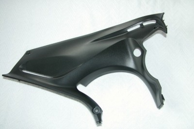
Finished hole in upper cowling.
Powerlett Wiring Harness Preparation-
Now you will need the RadioShack 12v powerlett, 16 inch lengths of red and black wire (14ga 600Ma) and the two small
electrical splicers (red rockets) and electrical tape. First splice the extensions to the end of the powerlett wiring harness.
Insure your splice is good (I soldered mine) and the caps are firmly retained, a firm slight tug on the splice suffices as a test.
Using the electricians tape, begin tightly wrapping the wiring harness (red & black) one inch from the powerlett.
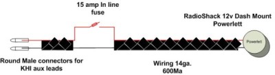
Electrical wiring diagram (not to scale and splice location not annotated).
Wrap until you a 2 inches from the inline 15 amp fuse where you will pull the red wire and fuse creating a 1-2 inch service loop
(explained in Harness Routing section). Wrap the tape 3 times around and then back towards the powerlett and cut the tape. Starting
on the other side of the service loop begin taping to the end of the wiring harness including the splices, leaving the last 2 inches
free. Strip ˝ inch of each wire, insert into male round ‘probe’ connector, crimp (press with pliers) and apply liberal solder to
each connection. You now have a an integrated wiring harness that is long enough to route back to the under seat KHI leads.
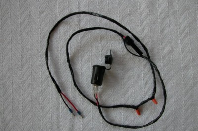
Completed wiring harness.
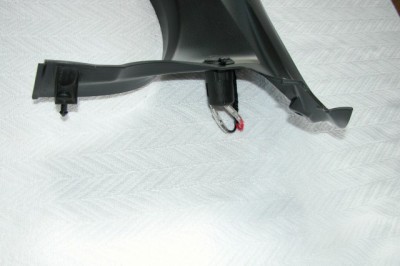
Powerlette installed showing rear view.
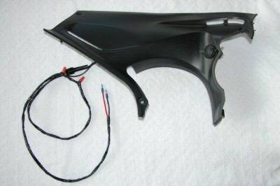
Complete harness and cowl ready for mounting and cable routing.
Harness Routing-
Take the side cowling and flip it over you will see the foam shield. Mount the two tie wrap retainers on along the right
side of the cowl, one on the side of the vent, and use a very tiny drop of Gorilla glue on each (otherwise the heat will cause
the adhesion agentof the wrap mount to eventually fail). Let the glue dry for 20 minutes before securing tie wrap mounts. Insert
the two tie wraps into the retainers. Pull the harness through the hole and snap the powerlett into place and lay the harness
across the tie wraps leaving a 3 inch service loop behind the powerlett.
The goal here is to get the fuse loop you created where it can be accessed through the top cowl lower (largest)vent to replace
a blown fuse without having to remove the plastic. Cinch the tie wraps and test accessing the fuse assembly through the vent and
pop the powerlett out to make sure you have enough length to service or replace the powerlett. Mount the cowling back on the bike.
It is a pain in the butt and patience is the watch word, especially fitting the plastic under the instrument cluster. Insure the
end of the harness comes out over the top of the main frame where it disappears behind the side cowling.
You may want to pop out the powerlett out while fitting the plastic. Once the plastic is remounted you will now route the
remainder of the harness behind the frame and under the gas tank (you should see a ‘raceway’ gap where other hoses and electrical
have been run. I recommend tying a piece of string to the end of harness so you can feed through to the forward edge of the battery
case. At this point you will pull it up and through the inside the tube frame on the left side and connect it into the leads (one
to the XX and one to the YY).
Using the third and final tie wrap to secure it to tube frame next to the KHI provided leads. Ensure you routed inside the main
frame (silver) and structure frame (tubular). Take your favorite device and plug it into the powerlett to test for power or use a
multi-meter you should see 12v. Congratulations you now have a power source next to your instrument cluster to power tank bag setups
and other touring accessories. Cool
Addendums-
- This powerlet is always hot regardless of key position in ignition.