Written By: Val
I heard about the Flo-Commander kit about the same time I bought my ZZR. I was both skeptical and
very curious as to whether the claims were real or if this was some sort of gimmick. I decided to
give it a try after Scott started carrying it in the site store. I first emailed the designer (Steve)
and gave him my number and expressed a desire to discuss the Flo-Commander further. He called the next
day and within 10 minutes he had convinced me that this was a well-designed and functional product,
but I still had my doubts. I then contacted a good friend (gear head) and explained what Steve had
told me and had him check his website. After he gave me a thumbs up I picked up the phone and ordered
the main circuit kit from Scott.
Tools and Parts
Assembly is very simple and can be accomplished by a novice mechanic. It took me about 2 hours but
I was keeping a log and recording pictures. Below is a list of tools that will be required:
- Drill
- Hammer
- 3mm, 5mm and 6mm Allen wrenches
- 8mm, 10mm and 7/16 sockets w/drive and extensions
- Phillips screwdriver large and small
- Razor blade or sharp knife
- Needle nose pliers
- Pencil
- Shop rags
(I also recommend having a magnet close because you never know when you will drop a bolt, but it is not required).
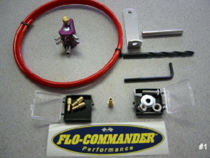 Remove the Flo-Commander Kit from the packing and inspect all the pieces. My kit came with:
- Ľ drill bit
- 42” tubing
- L bracket
- 4 tubing adapters w/ installation tool
- 1 button head bolt, 3 washers (2 sm/1 lrg) and 2 nuts
- Allen wrench (for button head bolt)
- Instructions
Disassembly
Before I start I like to have minimal gas in the tank (1 gallon). Turn the Fuel
petcock to off and allow the bike to run for 30 seconds. This will ensure you don’t
get any spillage when removing the fuel line.
- Remove seat
- Remove plastic (charcoal panels that surround the instrument cluster/ lower fairing panels
and side covers)
- Turn fuel off and remove knob - one screw in the shaft (Fig. 1)
- Remove toolkit holder - two 10mm bolts
- Remove fuel overflow line
- Remove bolts holding rear of fuel tank - two 10mm bolts (Fig. 2)
- Remove bolts holding front of fuel tank - two 10mm bolts (Fig. 3)
- Lift up on front of tank and place rag if worried about scratches
- Disconnect fuel gauge connection by depressing the detent and pulling. If you have trouble
finding the connection just lift up on the rear of the tank and trace from tank
- Disconnect fuel line using needle nose pliers (Fig. 4)
- Remove tank
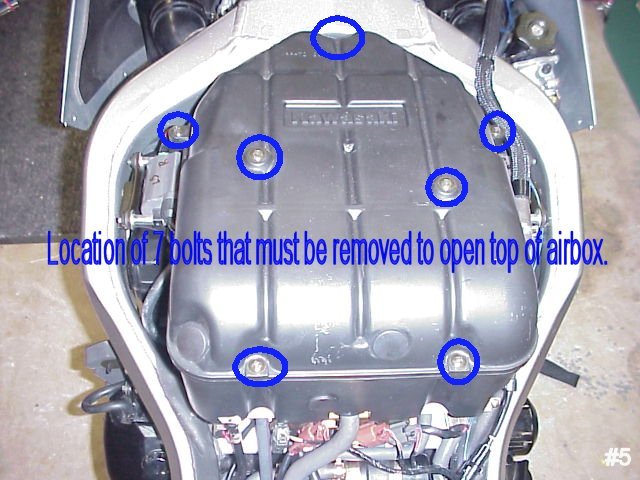
- Remove the seven Phillips screws securing the top of air box (Fig. 5)
- Remove air filter and screen
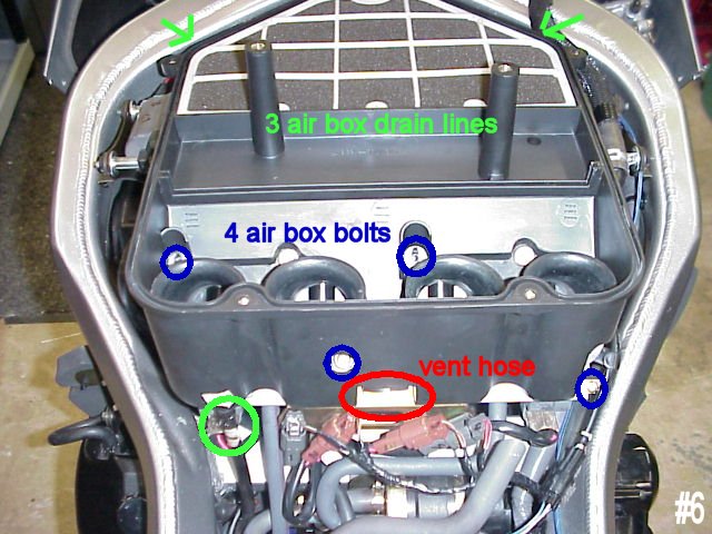
- Remove air box by removing the four 8mm bolts, three air cleaner drain hoses, and two vent hoses (one
can only be seen after you lift the air box). If you lift up on the rear of the air box and clear the
velocity stacks it will allow you to disconnect the 2nd hose. The ram air intakes will slide out of the
front of the air box (Fig. 6)
- Remove Velocity stack holder - four 8mm bolts (Fig. 7)
- Remove 4 Velocity stacks from holder by pinch the stack and pulling
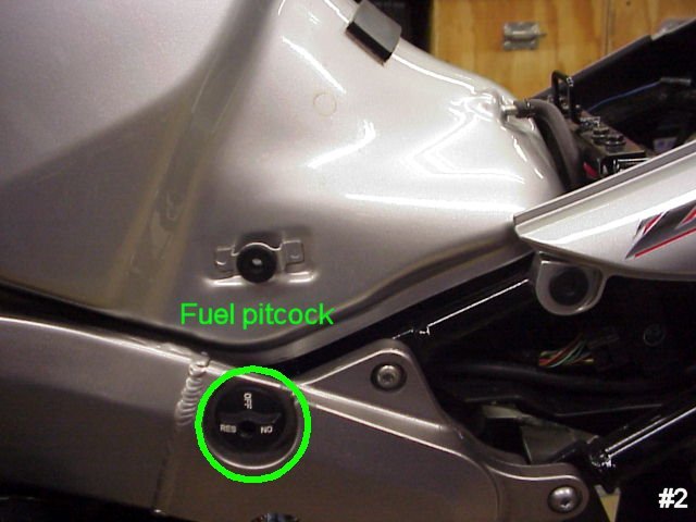
Fig. 1 |
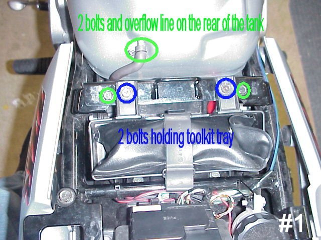
Fig. 2 |
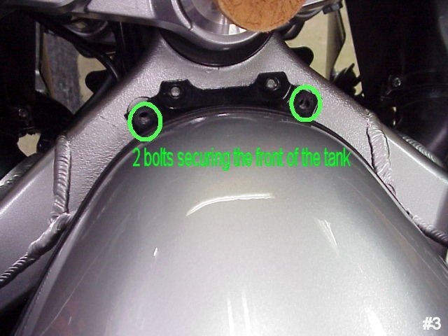
Fig. 3 |
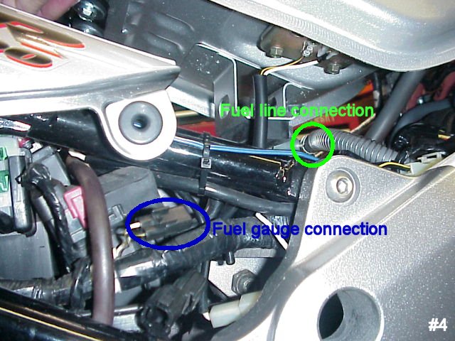
Fig. 4 |
Flo-Commander Installation
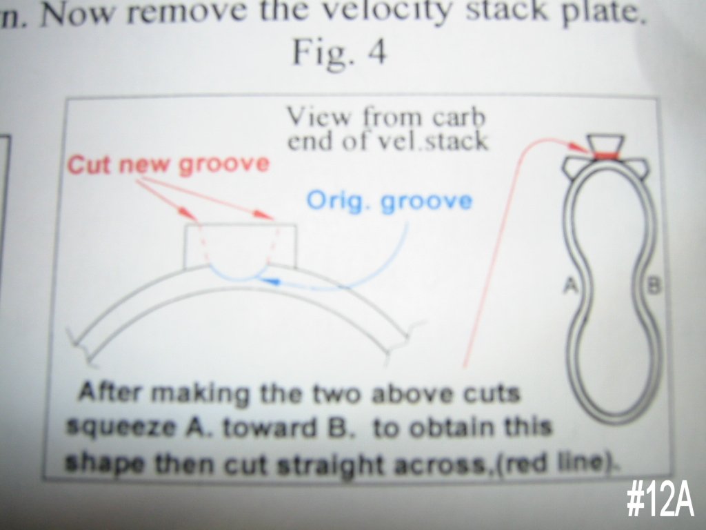
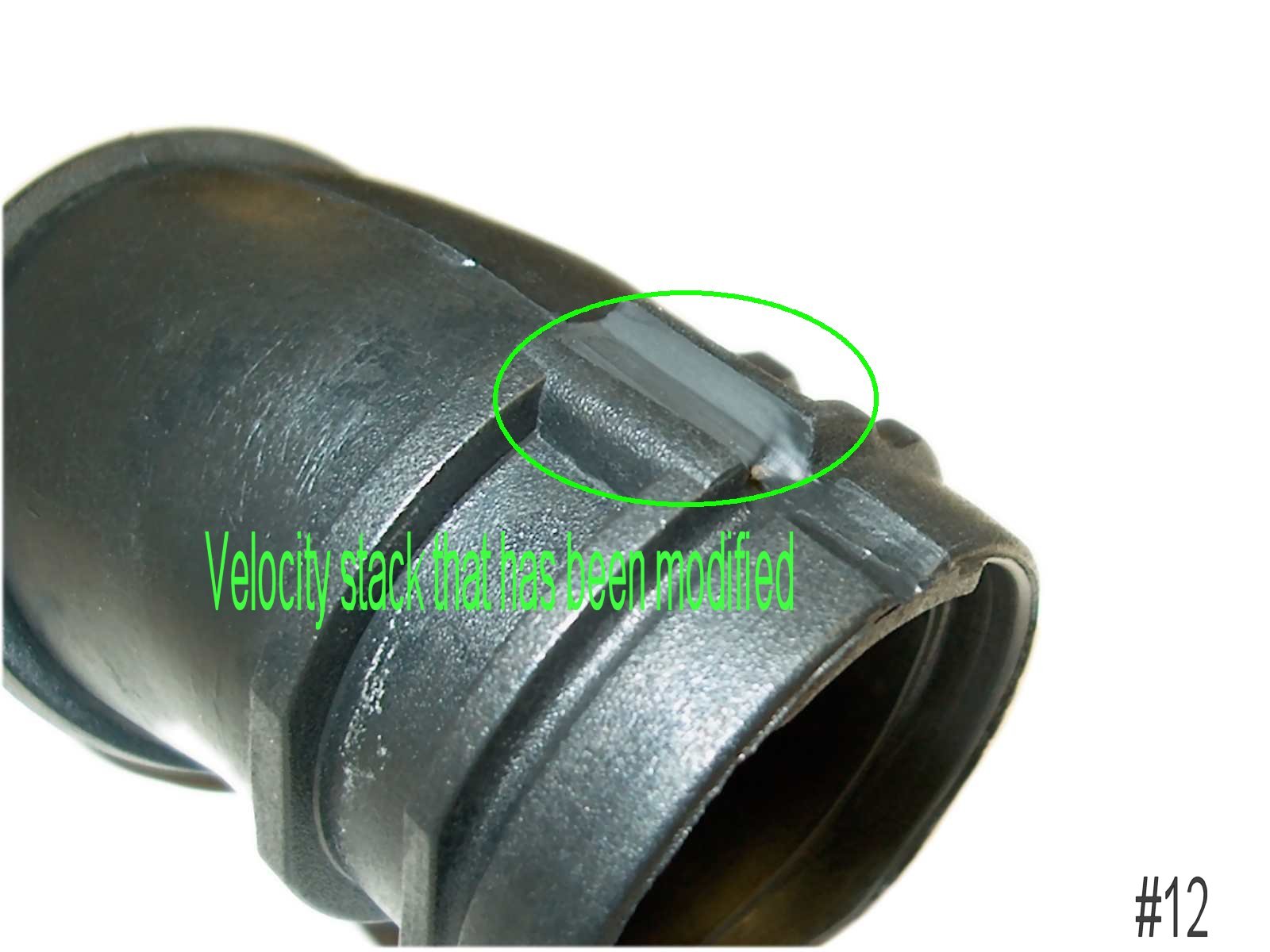
- Cut groove in each velocity stack. It already has a groove cut, you are just extending the
groove up the stack to allow clearance for the tubing adapter. If you use a razor blade, be careful
not to cut completely through the stack. The technique in the instructions, which I used, is to make
two 45 degree cuts and then squeeze the side of the stack. This will allow you to complete the bottom
of the cut (Fig. 8a & 8b)
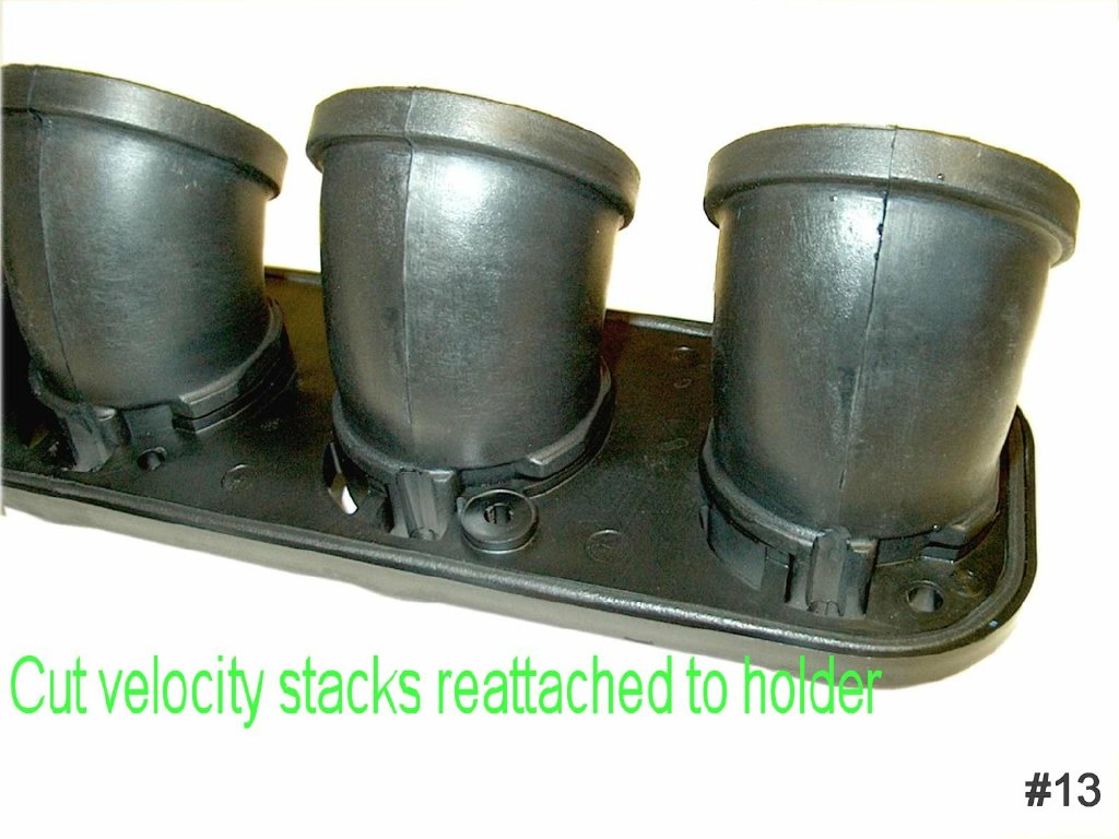
- Reattach Velocity stacks to holder and set on workbench by pinch the stack and pushing (Fig. 9)
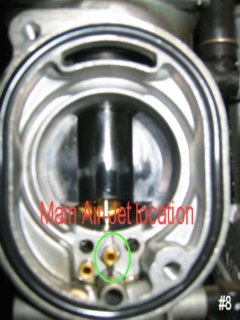
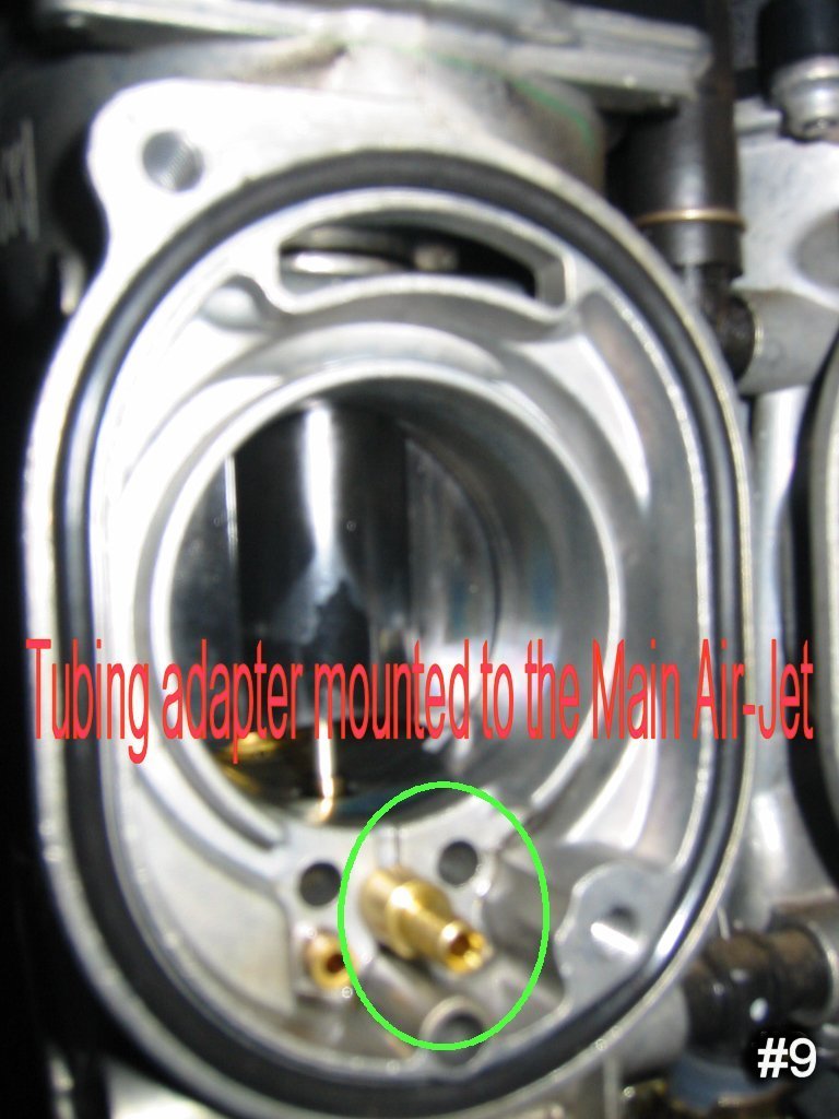
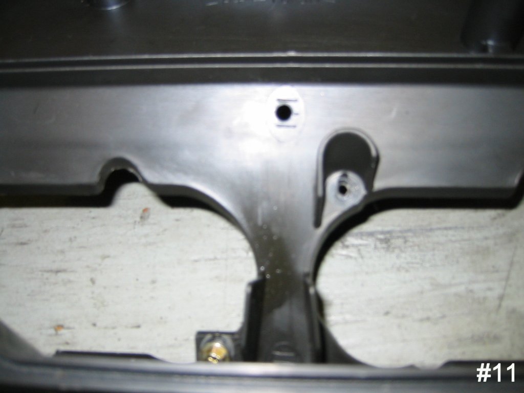
- Install tubing adapters (4) to Main Air-Jets. Start adapter by hand and then place installation
tool (provided) on adapter and tap gently with hammer until it seats (Fig. 10 & 11)
- Install velocity stack holder to the carbs and secure with four 8mm bolts (Fig. 12)
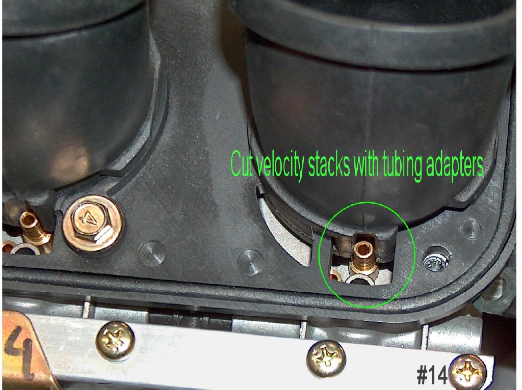
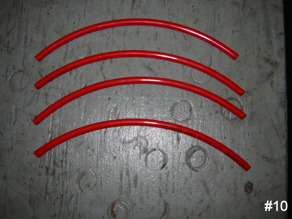
- Cut tubing into four 8” lengths (Fig. 13)
- Attach one 8” piece of tubing to each tubing adapter. The tubing will have a natural bend and should
be pointed up when seated on the tubing adapter. If working in a cold climate you may have to heat [be
careful not to melt] the end of the tubing up with a hair dryer or heat gun (Fig. 14)
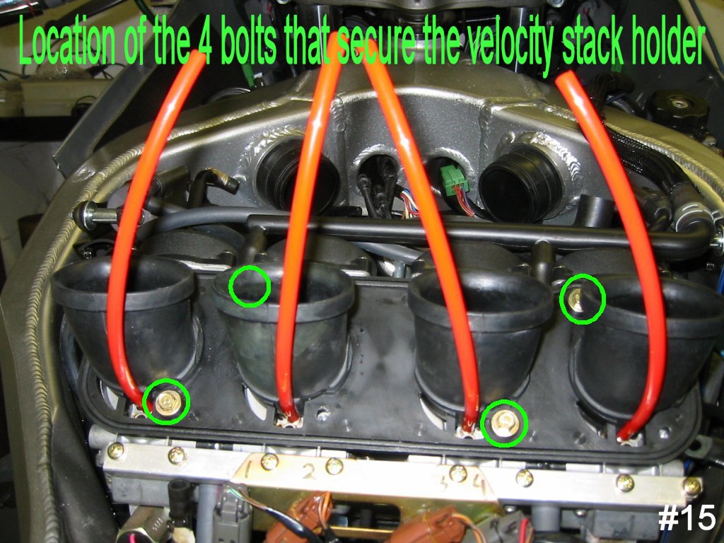
- Install the L bracket in the air box. Kawasaki made it easy for ZZR owners and left a molding imprint.
Place it on the molding mark and the back should be touching the rail for the screen. With a pencil
mark the location of hole and then remove the bracket and drill on the mark. Now flip your air box over
and remove any shavings and bugs you accumulated over the months (Fig. 15)
- Install the L bracket in the air box with the button head bolt, 7/16 nut, and washers. The larger
washer will go on the bottom of the air box with the nut
- Attach the Flo-Commander to the L bracket using the remaining 7/16 nut and washer. The nut and
washer will be facing the front of the bike and the Flo-Commander will be facing the rear. Don’t panic
when you see the photos. I was getting excited by this point and had already attached the air box to the
bike before I realized I didn’t have a photo (Fig. 16 & 17)
- Reattach the air box to the bike. Position the air box over the velocity stacks and attach the vent
line you couldn’t see on removal. Then lower the front of the air box. If the ram air ductwork is preventing
the air box from lowering you can move them towards the front of the bike. Then collapse the end of the duct
and feed it into the air box - four 8mm bolts
- Now attach the four pieces of tubing to the Flo-Commander. The outside lines (#1 and #4) are attached to
the bottom nipples and the inside lines (#2 and #3) are attached to the upper nipples. The instructions
recommended mounting the tubes to the Flo-Commander before mounting it to the bracket but I did it as described.
If your unable to get the tubing to properly seat on the Flo-Commander use heat. Inspect the routing of the
tubing now that it is attached to the Flo-Commander. Your Velocity stacks should not be distorted. The tubing
will be touching the velocity stacks but shouldn’t be pressing against them so hard that it completely distorts
the shape of the collar
- To adjusting the Flo-Commander turn the dial clockwise until it stops and then back it out (counter clockwise)
2˝ turns out (TO). I used 2˝ TO because I tested at 300 ft above sea level and the manufacturer recommends 3 TO
or 2˝ TO as a base setting. 2˝ TO will be a richer setting then 3 TO.
- If you're not going to run the bike on a dyno, then reassemble in reverse order.
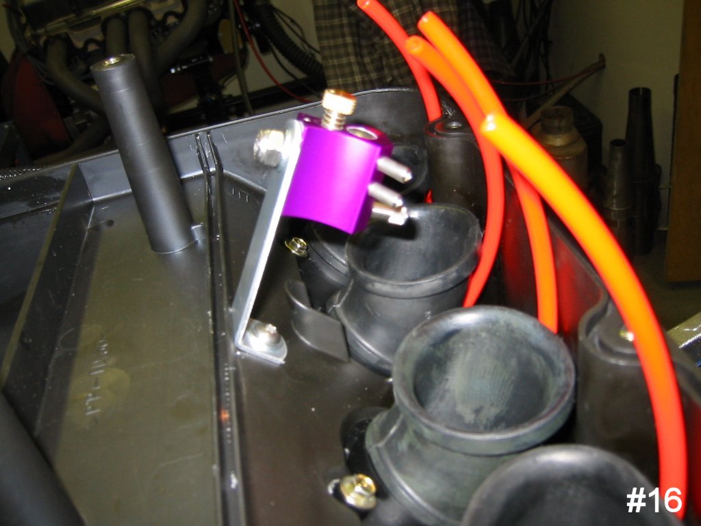
Fig. 16 |
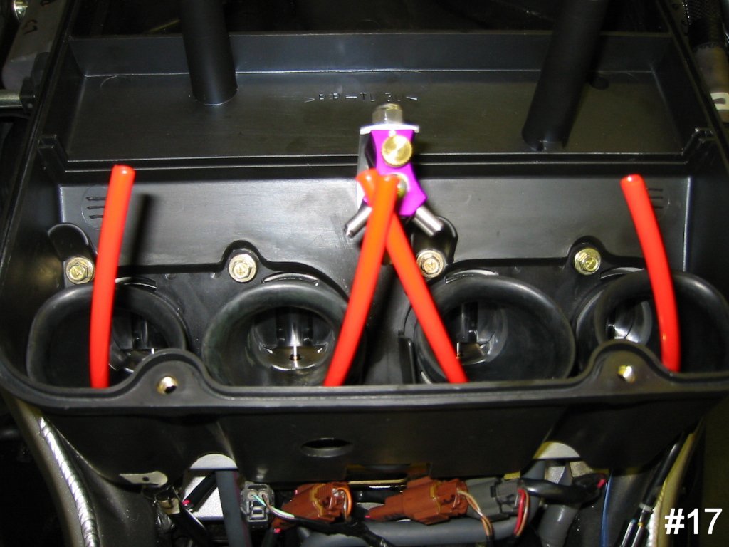
Fig. 17 |
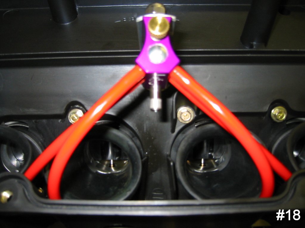
Completed Installation |
Dyno Results
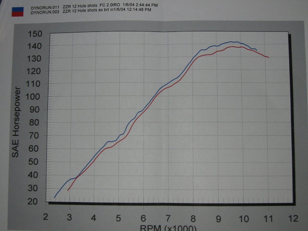 My first impressions are very positive and feel it has lived up to the manufacturers claims of more power
by synchronizing my carburetors. My first dyno run at 2˝ TO produced positive numbers (Hp & torque) throughout
the power band. I also tested 2 TO and 1˝ TO but found my best gain at 2 TO. Just because my bike performed
best at 2 TO, it doesn’t mean that 2 TO is now the standard for all ZZRs. My hypothesis is that my bike was
running slightly lean prior to the FC installation and this required the additional ˝ TO.
My first impressions are very positive and feel it has lived up to the manufacturers claims of more power
by synchronizing my carburetors. My first dyno run at 2˝ TO produced positive numbers (Hp & torque) throughout
the power band. I also tested 2 TO and 1˝ TO but found my best gain at 2 TO. Just because my bike performed
best at 2 TO, it doesn’t mean that 2 TO is now the standard for all ZZRs. My hypothesis is that my bike was
running slightly lean prior to the FC installation and this required the additional ˝ TO.
I would recommend this product to anyone without hesitation. --Val