Written By: helodoc
Here's my version of the Audiovox Cruise Control installation.
A note before you get started: To ensure reliability and maximum enjoyment from your cruise
control, please pay special attention to your electrical connections. Double crimp, solder,
and heat shrink tubing make for very strong and water resistant connections. Pay attention
to routing of wires, cables and vacuum lines. Properly shield all wires from heat and chafing.
Using spiral tubing and wire looming is a great idea as well as lots of electrical tape. Don't
pull your zip ties so tight that they pinch vacuum lines or wires. Also, absolutely make sure
that anything you install does not interfere with the normal functioning of any component on
the bike.
You need to strip the plastic off the bike. Inner Cowlings, Side Fairings, Gas Tank, and Battery
Covers all need to be removed. Remove the entire airbox, and velocity stacks once you get to them.
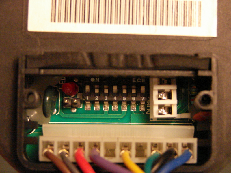
Before you do anything else, get the servo and remove the small cover on the back (2 screws)
and set the dip switches exactly like shown in the picture. This tells the servo, that the motorcycle
is an automatic car, and sets the proper sensitivity and RPM (hertz for our purposes). Also connect
the harness to the back of the servo and reinstall the cover. You could silicon seal it, but I never
did, and had no problems.
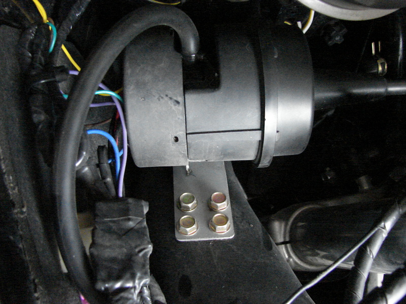
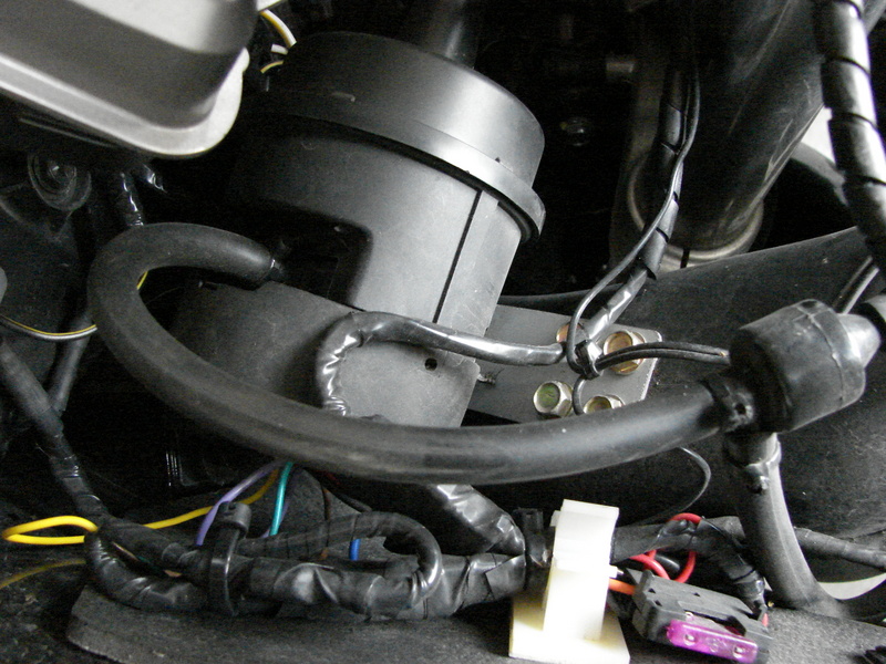
First, mount the servo on the left ram air tube. Drill four small holes in the ram air tube as
pilot holes in the bolt pattern of the bracket. Using the self tapping screws attach the servo. Be
servo is slightly angled so the cable will clear the steering neck.
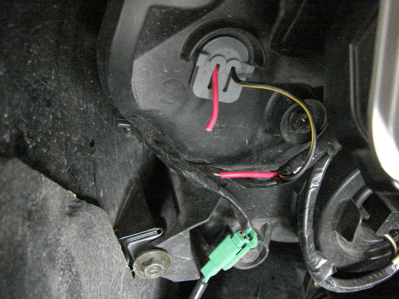
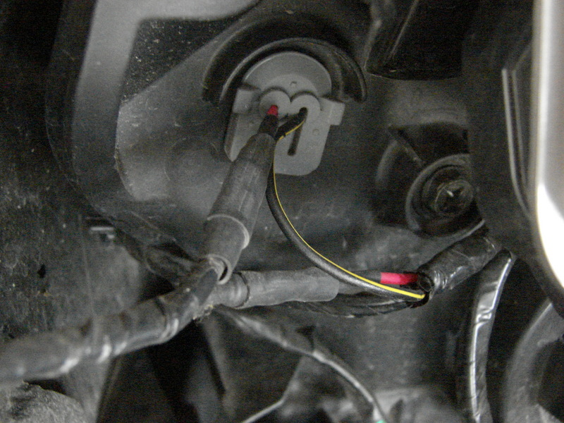
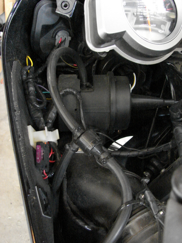
Next, connect 12V switched power to the system by splicing into the left front marker light. It's the red wire.
Then connect the orange wires from the cruise control harness to the marker light. 1 orange to 1 red, then 2nd orange
to 2nd red. I did this because Kawasaki left very little extra wire so I added some length.

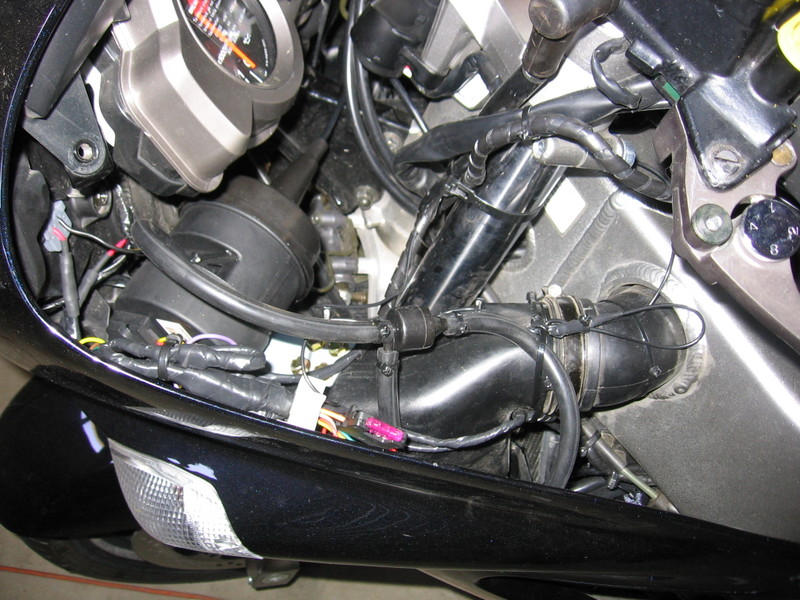
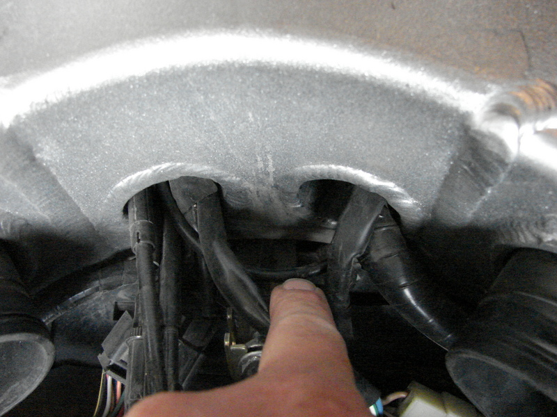
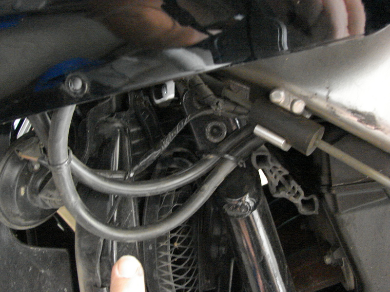
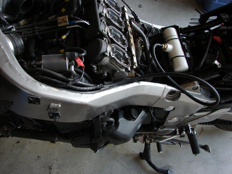
Next, route the servo cable. The cable is too long to run directly to the throttle arm, so you have to make a
complete loop through the frame pass throughs and back around under the steering head, then slide it over the top
of the radiator and between the frame and the valve cover. There is very little room but it will fit if you slide
from left to right.

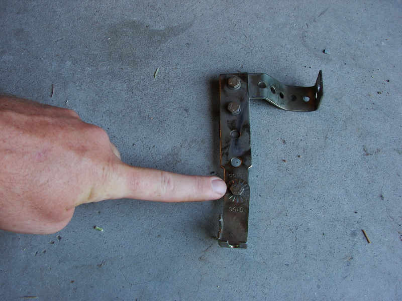
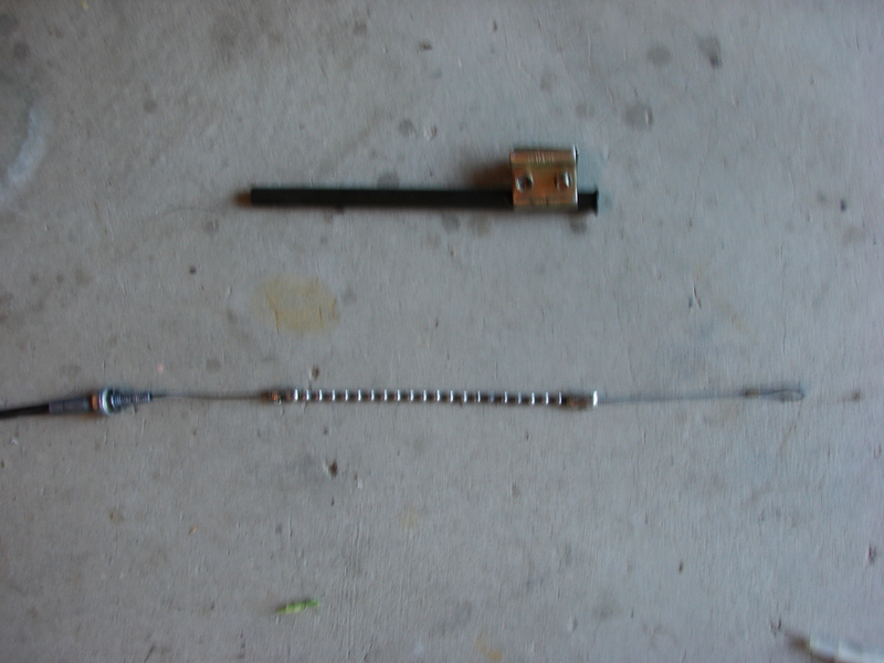
Disassemble the servo cable bracket (remove the bolt). For guys installing a new kit, you will have to bend the stock
that comes with the kit in order to make this bracket. The metal isn't very hard. I bent this one into shape using a vise
and my hands.
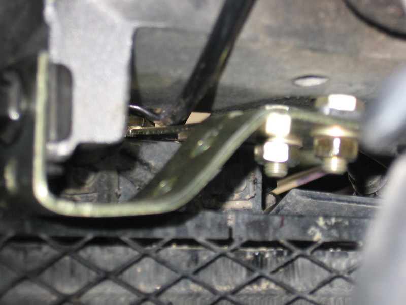
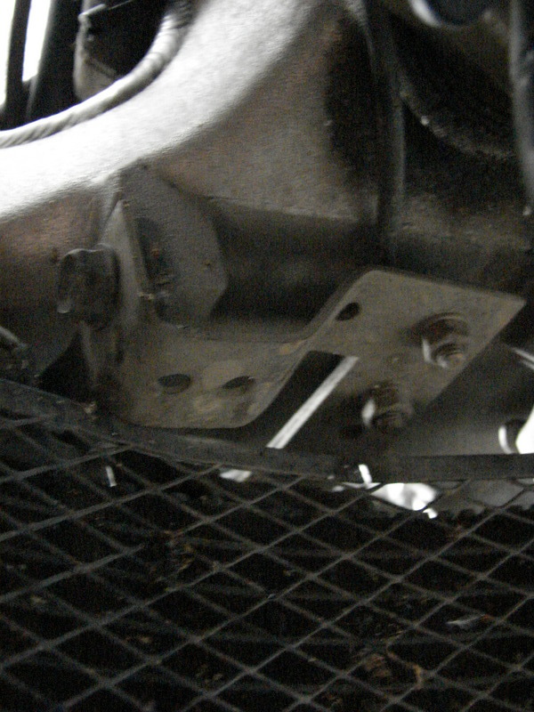
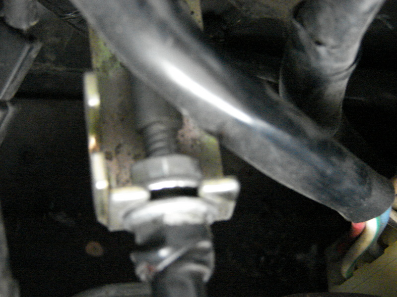
Remove the right upper radiator bolt. It's accessible if you turn the bars to the left, then follow the right fork up.
Slide the servo cable bracket (the one above) into the small gap between the top of the radiator and the frame. Use the
stock radiator bolt to attach the bracket (use some locktite 242). You could get a longer bolt, but in 20K miles I never
had a problem. Once this part of the bracket is bolted down reattach the part of the bracket you removed. It will now be
above the valve cover.
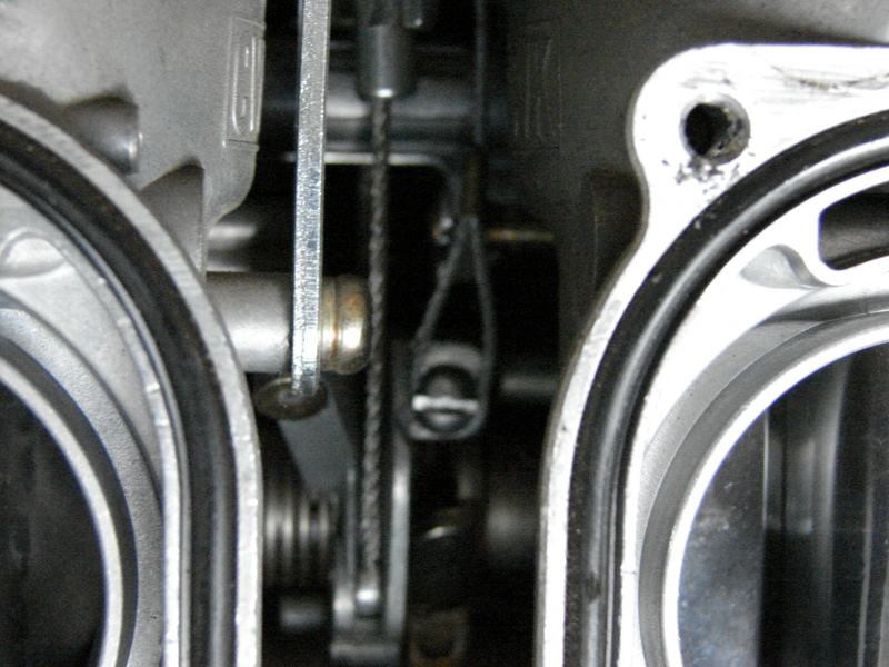
Here's the hard part: You will need to drill and thread a hole on the throttle arm. Please make sure
you have the screw selected you wish to use and the proper drill bit and tap. It's a real pain to get into this tight
spot, but it can be done. Have someone hold the throttle "full on" and the place you need to drill becomes more accessible.
you also might want to cover the carbs. openings. Drill and thread here..
Once that hole is drilled and threaded slide the piece of green aluminum tubing over the dog chain and lanyard. Make sure
the jamb nuts are in place on the threaded end of the servo cable sheath before hand. If you have a new kit, you will need
to fabricate this piece. 5/16 inch I.D. pre-flared aluminum tubing from the auto parts store, cut to approx. 8 inches long.
Some folks have had success with not using this piece, but it seems there is a lot of stuff to snag the chain on the valve cover.
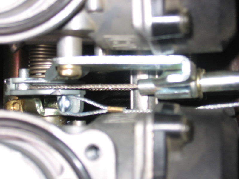
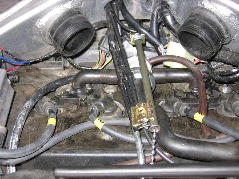
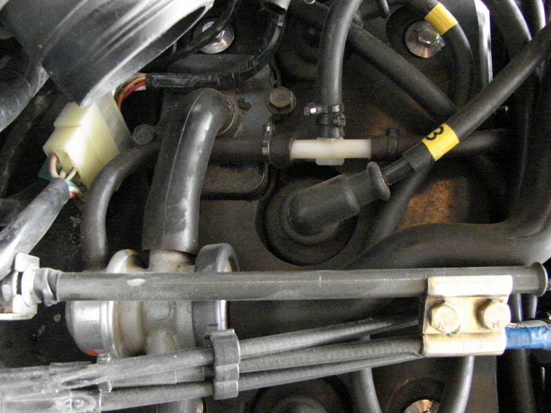
Slide the servo cable into the forked end of the bracket you previously installed. tighten the Jamb nuts (one on either
side) to secure the servo cable. Put a few wraps of electrical tape on the aft end of the servo cable sheath, making sure
the tape isn't on the cable. Force the shielding tubing (green tube) into the jamb nuts (and electrical tape) of the servo
cable and use the clamp in the picture to hold the shielding tube to the throttle,return, or choke cable. Don't over
tighten it as you can damage the throttle cable. Again locktite 242 is highly recommended here.
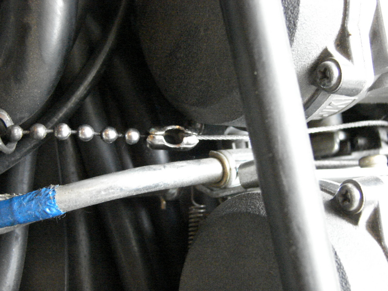
Now attach the lanyard to the hole you drilled in the throttle arm. Again have someone hold the throttle "full on".
If you have a new kit attach the lanyard first. Use locktite 242 on that screw, the attach the dog chain to the lanyard.
It may be necessary tho remove several beads (links) from the chain. [u]You want it tight enough that when the throttle
is released the servo cable does not hold the throttle open at all.[/u] But you don't want a bunch of slack either.
Now attach what will be used for the "speed sensor". Find the blue wire on the cruise control harness that has the
noise suppressor in line.
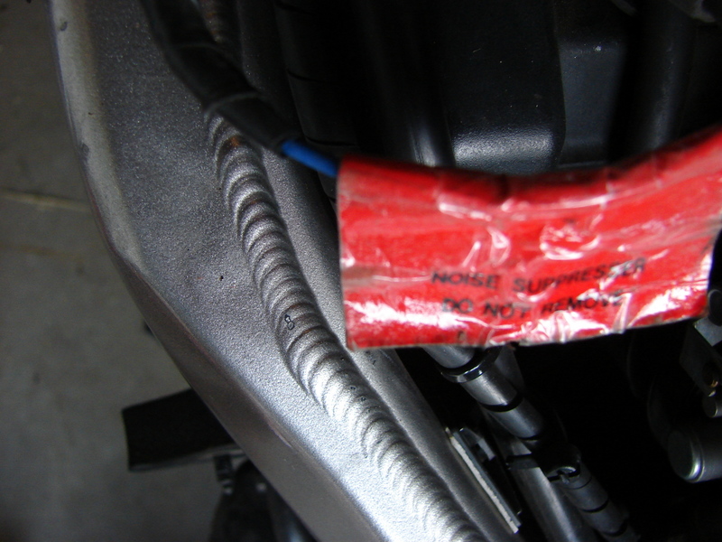
Splice this wire into the "Input" for the left side coil. Use the lower wire on the forward side. Sorry I can't remember
the color, but Kawasaki used several different colors depending on year. The lower wire is the one to splice into. Be sure
your connection here is flawless, crimp solder, and heat shrink. If this connection fails on the road. bike no worky.

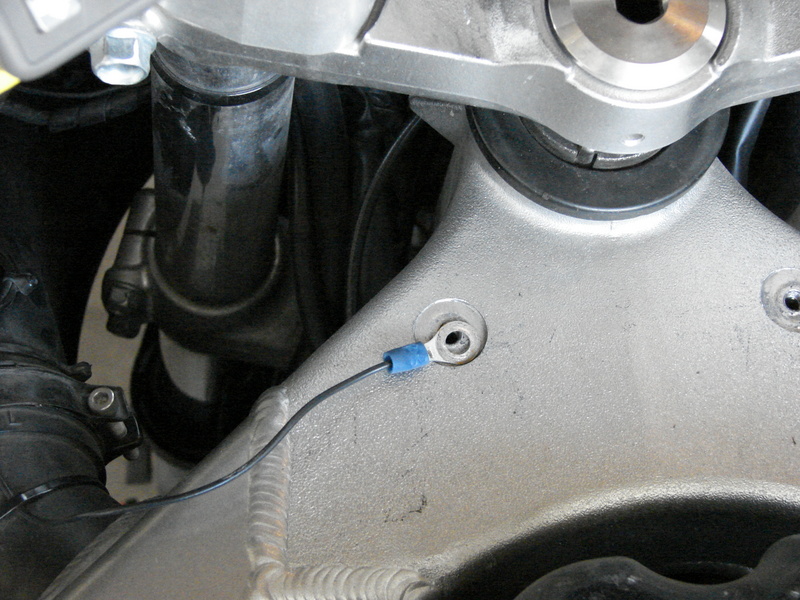
Find all the electrical grounds and splice them into a single ring connector, leaving enough slack to use the left
forward gas tank attachment bolt as the chassis ground. The connector should be directly in contact with the frame.
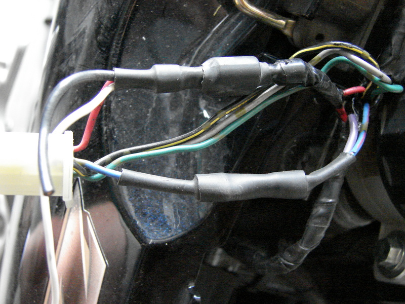
Next, find the wires on the cruise control harness that cause the cruise control to disengage when a brake is applied.
They are the purple and the red wires. One wire gets connected to the tail light which is a 12V constant, and the other
get connected to the brake light which is a 12V only when the brake is applied. I don't remember which is which, but I
do remember the connections. If in doubt, you can use a multimeter at the molex plug on the right side of the bike that
allows removal of the rear plastic. Connect the red wire from the cruise control to the red wire at the molex connector.
I believe this is the tail light (constant 12V) then connect the purple wire from the cruise control to the blue with red
line wire from the motorcycle. I believe this is the brake light. This system has a triple safety, so if you get this
wrong the first time, it won't kill you. Just pull the clutch, the rpm will rise and the cruise will disengage. Or just
reach over and turn it off!
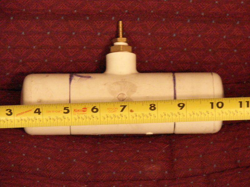
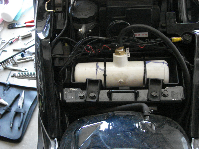
Now run the vacuum lines. I chose to use a vacuum reservoir, but it will work without it. The reservoir dampens out
oscillations cause by low vacuum conditions that exist is motorcycle engines. I used PVC pipe and fittings all found at
home depot. This installation covers use of a vacuum reservoir. If you choose not to use one, simply connect the Servo
canister to the vacuum bleed taken from the motorcycle.
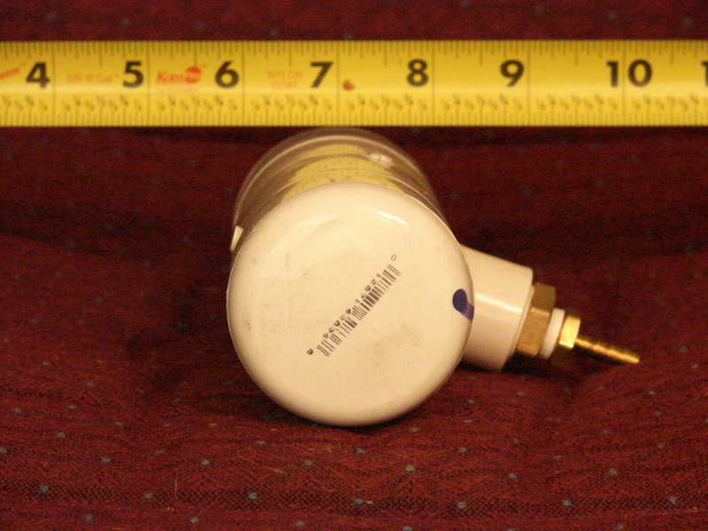
Here's the vacuum canister. Be sure to use the PVC prep and glue. You don't want any leaks! This canister is made to
fit in the tool tray under the seat. But you can make one any shape and size to fit anywhere you think you can stuff it.
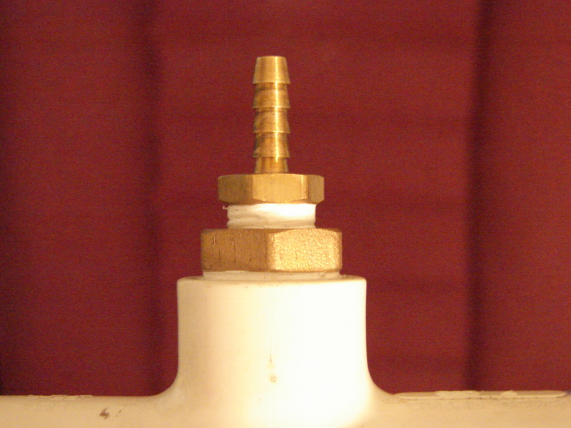
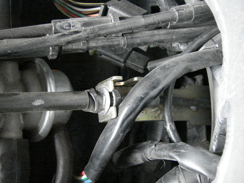
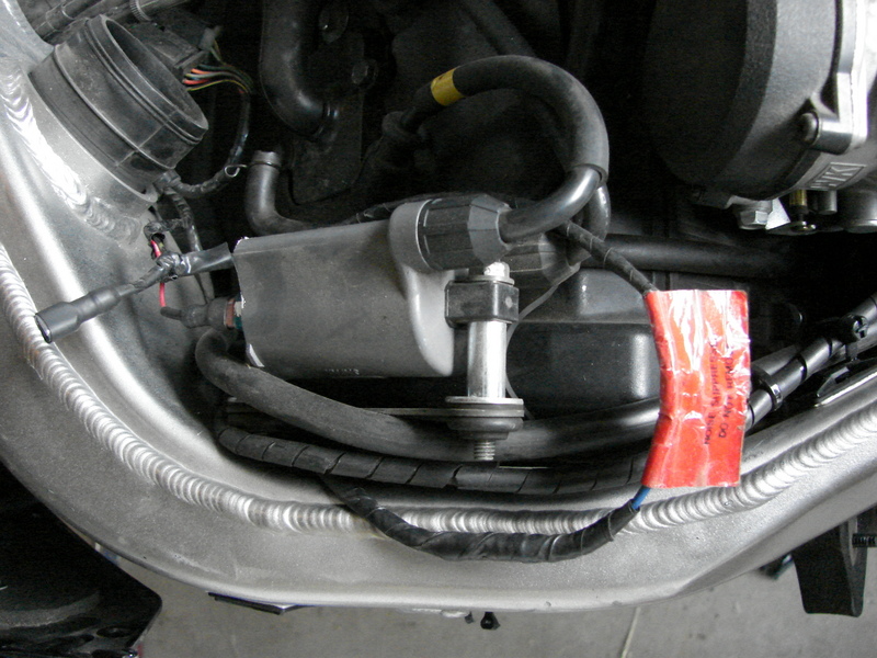
Buy a three port vacuum check valve, and a "T" connector for vacuum lines, and some (several feet) small bore
thick walled vacuum line at Napa. From the servo, Run about 6-8 inches of vacuum line and connect the check valve
(direction matters use the side with two ports) to this line. Starting from the other end of the check valve use
several more feet more of vacuum line and route the the line as shown in the picture below. Then use the T connector
splice into the vacuum line also shown in the picture below. This provides the vacuum to "hold" the servo at speed.
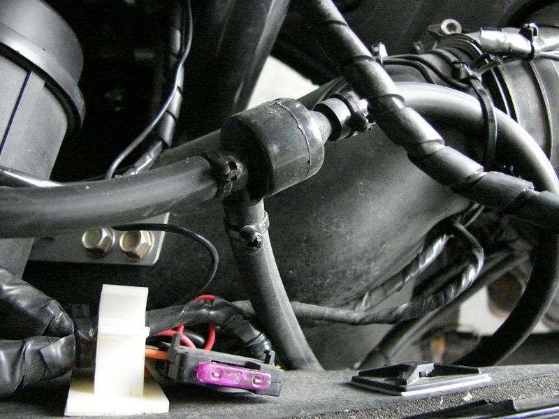
See the T connector, here is where you will bleed vacuum from the bike.
The last remaining port on the check valve ( the one on the side) will get connected to the vacuum cannister.
I routed it along with the vacuum bleed line to the valve cover, went under the left coil way down on the frame
cross member behind the engine, then left enough slack so that once the tank was installed, the post for the fuel
selector knob is above the vacuum line. Then up to the tool tray. Leaving just enough of a loop as not to kink
the line or get pinched when the seat is installed. I used some neoprene and zip ties to hold the canister in the
tray.
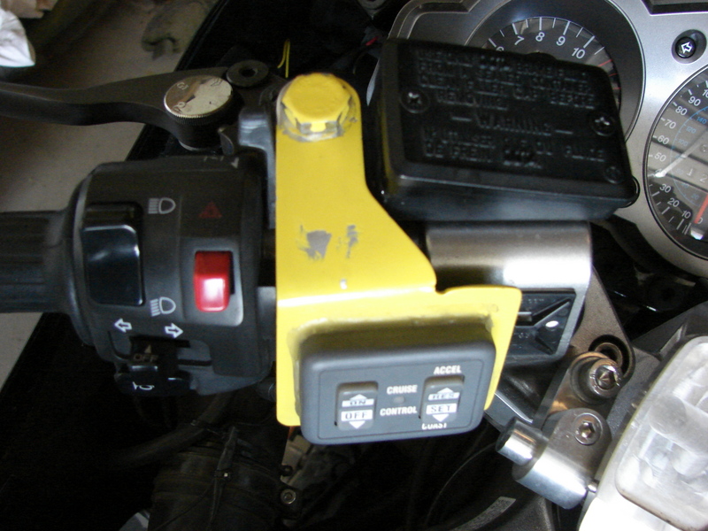
Finally mount the control pad by the left grip, using the hole for bar mounted mirrors. I fabricated this
bracket out of .061 inch aluminum. I didn't orient the control pad on the bracket the best way possible. I should
have turned it side ways for easier access, but I have big hand so not that big of a deal. Do what works for you.
Put the bike all back together and go for a ride. Because of the method for speed sensing we are using, the
cruise control can be jerky at low speeds. Always make sure you are in top gear. When setting the cruise control...Turn
it on, hold steady with the throttle, and hit set. Slowly release your grip with the right hand. The speed will probably
dive up to 7mph, but it will "catch" and recover to within a mph or two of where you set it. After getting used to the
operation of the cruise control, you can pretty much get a feel for it, and engage it with little or no speed loss. It
will hold within +/- 2 mph of where set. I'd suggest not using the "accel" button, as this puts stress on the servo.
Rather turn it off, the back on and hit "set" again. If you can't get it to set exactly where you want it, then use the
"accel" button to gain a couple mph. I've had this cruise control set at over 100 mph and it held perfectly, but if
you set it at 80 mph and try to use the "accel" button to get to 100 you will run out of servo.
Good luck and be safe.